Circuit's component representation and schematics
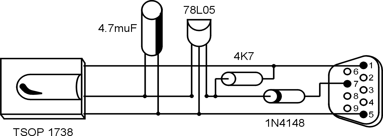
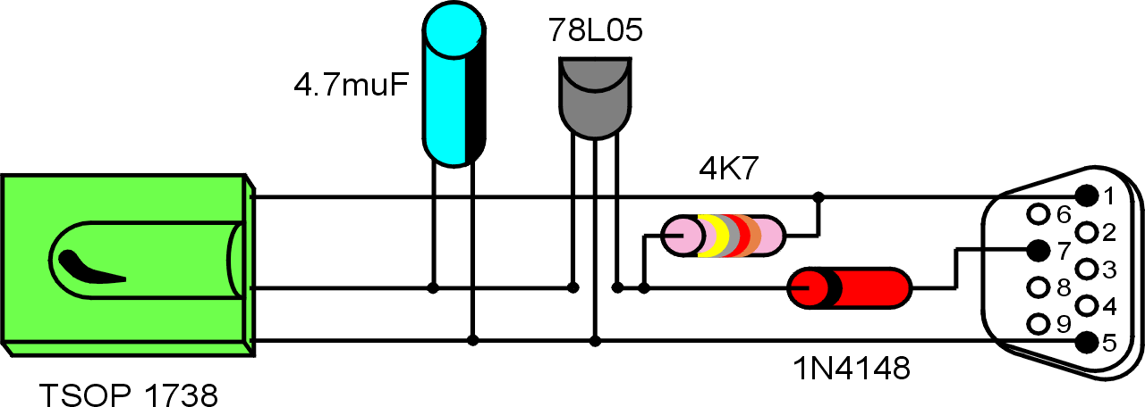
This is the component representation of the circuit, just to give you an idea on how the pieces will be mounted. The real schematics are below. It is possible to download the drawing in Eps format.
This is the real schematics of the circuit:
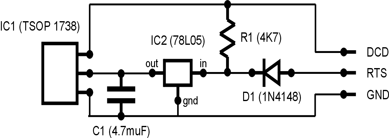
The description of this circuit is rather simple. The RTS line of the serial port gives power to the voltage regulator which fixes it to 5 stable volts. A diode is there to protect the serial port from inverse current. The capacitor helps to keep a stable voltage; all the grounds are bound to the GND line of the serial port. The data output of the IR receiver is connected to the DCD line of the serial port together with a pull-up resistor coming from the power line.