Capacitor and Wire
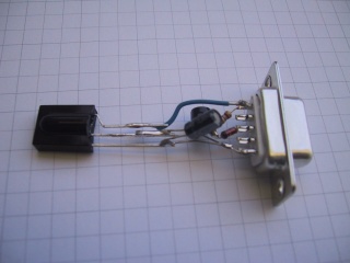
We now mount the capacitor between GND and the output of the voltage regulator, and the wire from the data output of the IR receiver to the DTS of the serial connector.
We prepare the wire in such a shape that it can easily go from the 1st pin to the data pin of the IR receiver; then we solder it: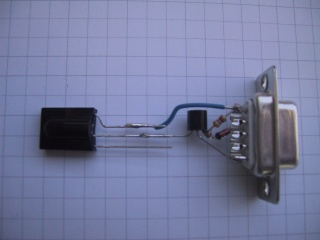

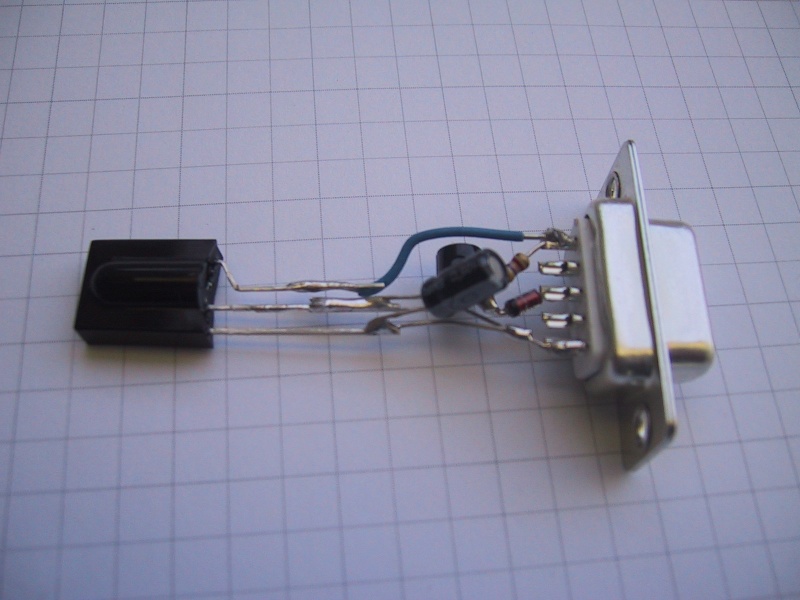
Now we must accurately prepare the pins of the capacitor in this funny way; have a look at the next picture also to better understand how it has to be mounted: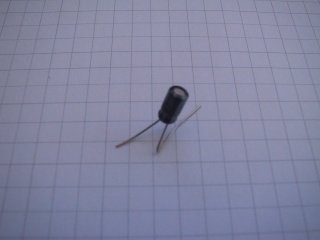
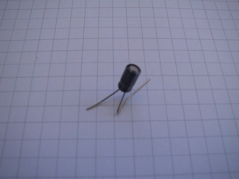
The positive pin of the capacitor must be soldered to the central pin of the IR receiver, where it is also connected to the voltage regulator. The negative pin must act as a bridge between the GNDs of the IR receiver and of the Voltage Regulator, going to the 5th pin of the serial connector: